Cruz Control (Patent 17/142,053)
Cruz Control is a entrepreneurial startup that applied and was accepted to work with Generate (NU’s product development studio), where I worked on a team with fellow engineers to design a custom skateboard brake
The brake would mount to the back of the board with a flexible spring steel for deflection, but not deformation.
I worked on two sections of this project: braking mechanisms and spring steel. I had to switch team’s halfway through the project to balance the experience of the team.
Problem and Client Goals:
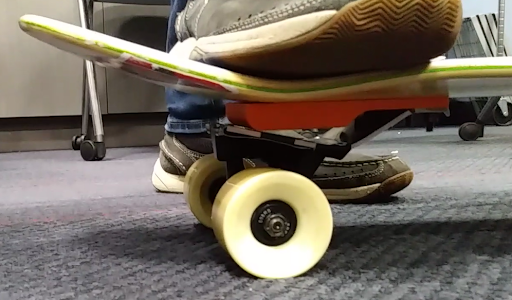
Skateboarders would ruin the bottoms of their shoes braking their skateboards. Custom skateboard brakes were cumbersome and prevented user from performing tricks at skate parks.
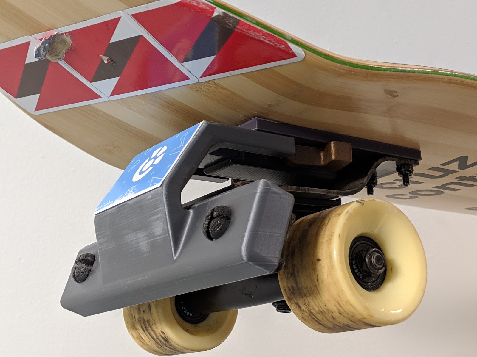
Client wished to create a removable skateboard that would function by the user applying force to the back of the board to push the brake against the wheels and return to normal shape after. Additionally, client wished to have “pop” or a boost whenever performing an ollie.

Skateboarder performing a foot brake
Clip of a Skateboarder performing an ollie
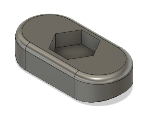
CAD model of the first iteration of brake pad (Top View)
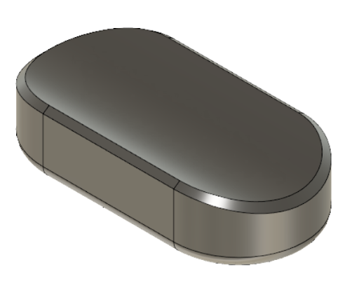
CAD model of the first iteration of brake pad (Bottom View)
Braking Mechanism
Problem:
The skateboard needs to be braked whether braking against the ground or the wheels. The rubber should only be changed at the same frequency of wheel bearings (3-6 months). Brake pads should be adjustable for different weight riders
Actions (Research/Brainstorm):
Researched the basic durometers of skateboard wheels and of easily moldable rubbers.
Began design on first iteration of brake pads
Actions (Design):
Designed first brake pad design for proof of concept.
Design Considerations:
Brake pad has 3 designs where 3 radii curvature matches of the 70 mm, 75 mm, and 80 mm radius of common skateboard wheels.
Brake pad was 2 inches width which is the average thickness of skateboard brakes
Fillets are placed around the design to avoid stress concentrations especially when braking.
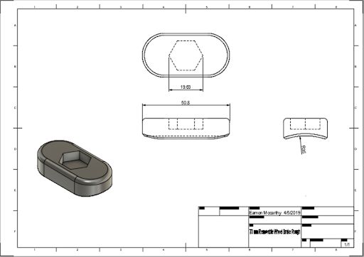
CAD Drawing of 70 mm diameter wheel brake pad
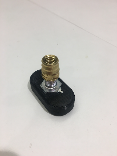
Assembled proof of concept for brake pads
Results (Manufacturing and Prototyping):
3D printed brake pads to perform a proof of concept of adjustable design and varying wheel radii
Hex bolt was glued into hex head cut to screw into heat set inserts. The heat set inserts would be screwed into buckle component. The user would be able to adjust the distance from the wheels of the braking mechanism using the screw.
Before I could further my design, my project lead asked me to switch teams to help with the spring steel.
Problems and Solutions:
Problem: Lots of stress on singular bolt for braking
Solution: Larger diamter bolts were used with adjusted hex head size
Problem: Possible unscrewing of bolt during riding and braking
Solution: In process of designing a flat which would have a set screw against it to lock bolt in place.
Spring Steel Mechanism
Problem:
The skateboard needs to be braked through compression. After braking, the device needs to return to its normal position. The reason I was switched because the spring steel would not deform properly
Actions (Research):
Because I came into process halfway through, I had to catch myself up to the work already done. Basic dimensions were created by the previous team. 1075 spring steel was used for the bending.
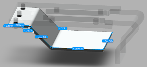
Spring Steel dimensions with bends CAD model
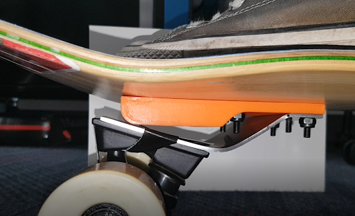
First spring steel testing (no deflection, only plastic deformation)
First spring steel testing (no deflection, only plastic deformation)
Actions (Problem Identification and Solution):
The two main problems were finding the right spring constant for the elastic deformation and thickness to assist in bending.
These two variables would cause the spring steel to plastic deform and not pop back into shape as seen in the photos
Actions (Testing):
I created an ANSYS program to perform FEA on the spring steel sheet. The spring steel was secured in 1 and 2. A 250 lb force was split evenly to simulate the force of the rider onto the mounted steel. This was a safety factor of 1.5 to account for all rider weights. The max deformation at point 6 was recorded.
I varied the thickness of the sheet in order to find the optimal thickness of the sheet which was 0.187 inches thick.

ANSYS analysis of spring steel bends
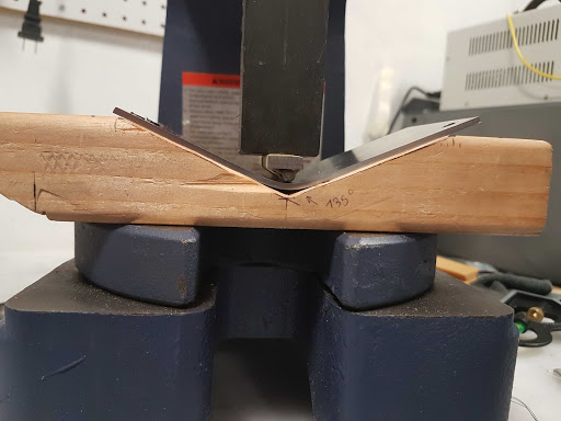
Spring Steel being bent on 2 ton arbor press
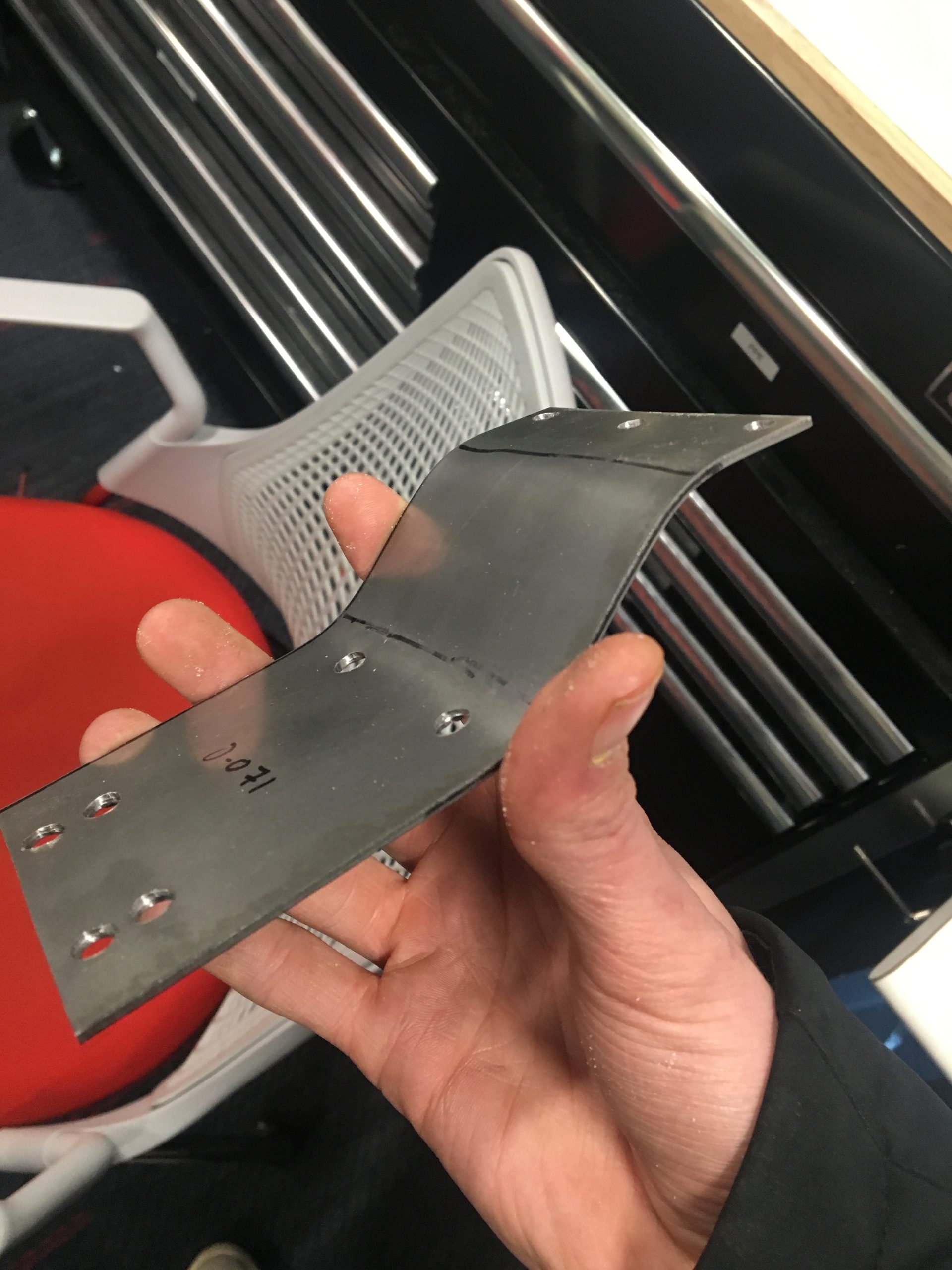
Spring Steel test bend with drill holes
Actions (Manufacturing):
We got the spring steel cut at the Northeastern Capstone Machine Shop and the holes drilled and tapped during the drilled presses.
The 0.187″ thick spring steel was difficult to bend using the 2-ton arbor press. But through trial and error the process was refined where wooden blocks were used for the bend angles and dowel pins used to create the radii of the bends
Actions (Redesigning):
Even after using the thickest piece of spring steel, the proper elastic deformation was not being achieved by this spring steel.
Upon further research, it was realized that this 1075 spring steel required heat treatment to acquire spring. I began researching how to heat treat spring steel and contacted the 3DExperience Lab at Dassault Systemes.
Using contacts at my DS from my coop, I knew there was a furnace there that could be used to heat treat. I scheduled a time and drove out to Waltham to heat treat the steel successfully.
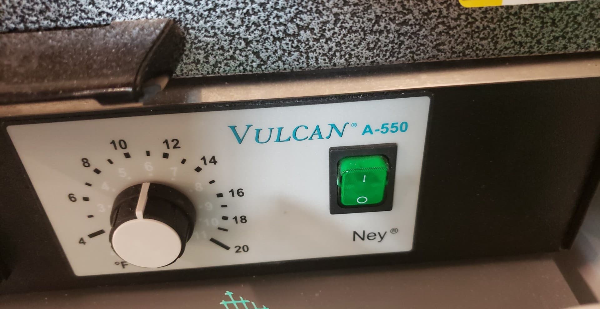
Furnance used at the 3DExperience Fab Lab

Full Generate Team with Clients at Showcase and final prototype
Results:
The heat treating was successfully in giving the spring steel the required spring to elastically deform! This steel was tested and handed off to the clients at our showcase.
Final Product:
After handing off the steel, it was discovered that 1095 Spring Steel would be a better steel to be used. While 1075 Spring steel was handed off to client, it was recommended to use 1095 for the future products.
Patent Application
Nearly a year later, the client approached our team to inform us they were moving forward to secure a patent of their designs. These designs included elevated boards and the skateboard accessories (our brake).
My team members and I were added to the patent for the future of the designs. The client will continue to grow their business in California.
Patent Information:
U.S. Application No. 17/142,053
Filing Date: 1/5/2021
Title: Skateboard Systems And Methods
PCT Application No. PCT/US2021/012215
Filing Date: 1/5/2021
Title: Skateboard Systems And Methods
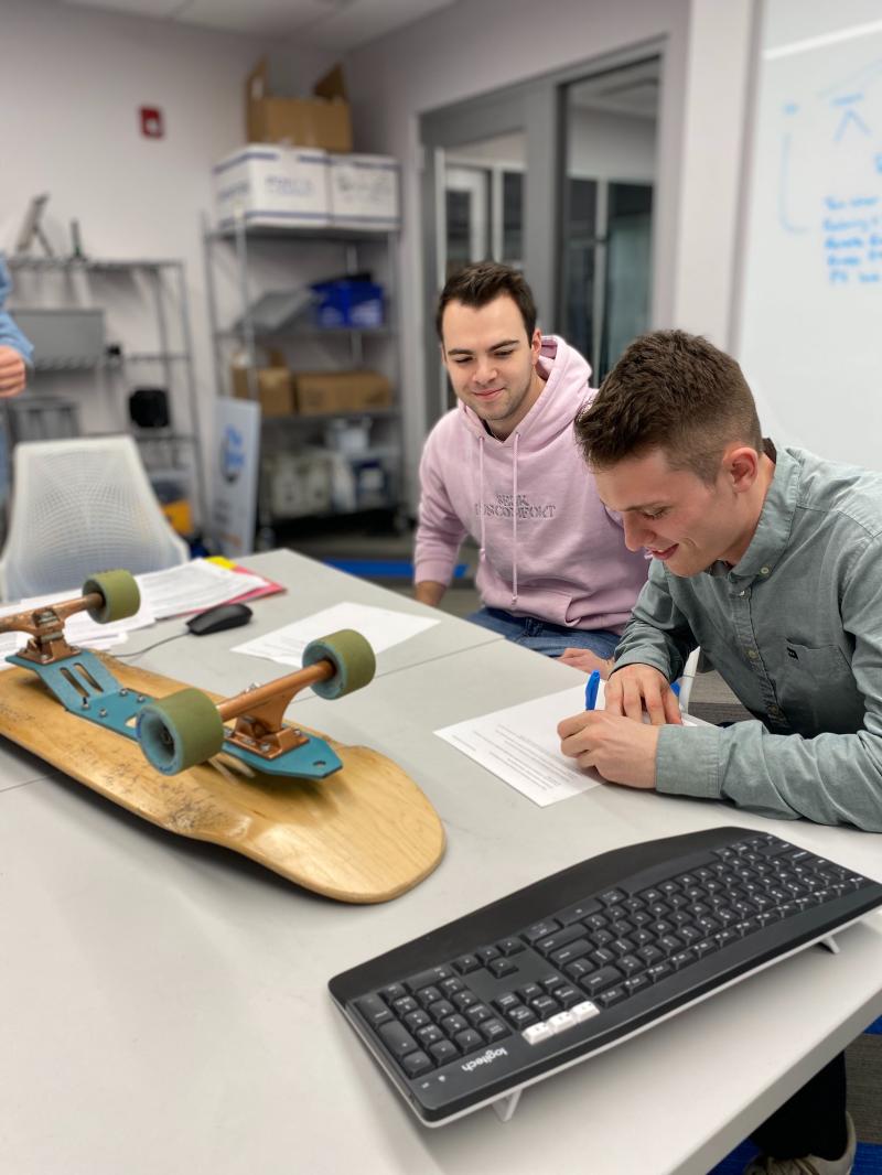
Patent Signing of the device